The Arduino MEGA was announced officially on March 26th, 2009. The MEGA kept the odd pin header spacing to make it compatible with most Arduino shields. But unfortunately, some pins had to be moved and this movement made some shields that use SPI incompatible. One of the most popular shields, the Arduino Ethernet shield is one of the incompatible shields, as it relies on SPI for Arduino to Ethernet communication. The good news is that it is possible to make it work with the MEGA and here is the procedure:
Ingredients
- Arduino MEGA board
- Arduino Ethernet shield
- 4 x male2male jumper wires
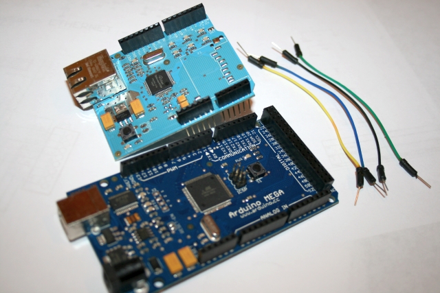
ingredients
First the Hardware hack
The SPI signals SCK, MISO, MOSI and SS are located in pins 13, 12, 11 and 10 on the Arduino Diecimila/Duemilanove or compatible boards like freeduino and seeeduino.
These signals moved to pins 52, 50, 51 and 53 on the Arduino MEGA.
Signals SCK, MISO and MOSI are available in the ICSP 2×3 pin header also, but signal SS is missing from this header, and only available on pin 53.
As the Arduino Ethernet shield expects to get these signals from pins 13 to 10, we need to re-wire them to pins 50 to 53.
First, we need to disconnect pins 13 to 10 in the Arduino Ethernet Shield:
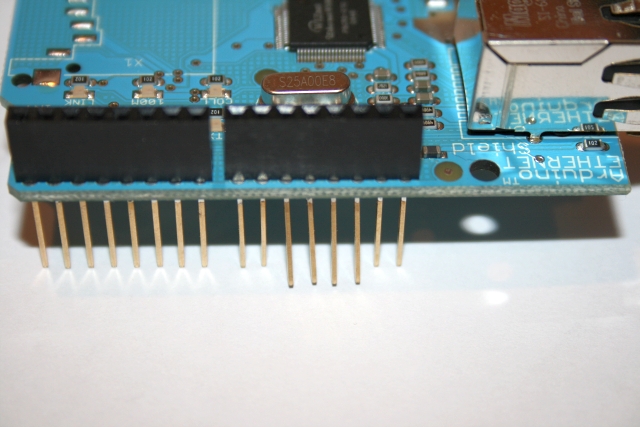
these4pins
Bend them slightly to the outside:
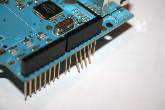
these4pinsside
And plug the Arduino Ethernet shield to the Arduino MEGA, so these 4 pins remains unplugged:
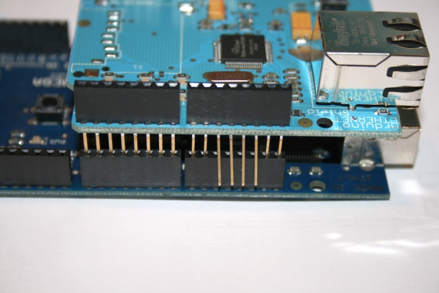
plug
Now, how are we going to get the SPI signals? From pins 50 to 53… following the next mapping:
MEGA pin 50 (MISO) to Arduino Ethernet Shield pin 12.
MEGA pin 51 (MOSI) to Arduino Ethernet Shield pin 11.
MEGA pin 52 (SCK) to Arduino Ethernet Shield pin 13.
MEGA pin 53 (SS) to Arduino Ethernet Shield pin 10.
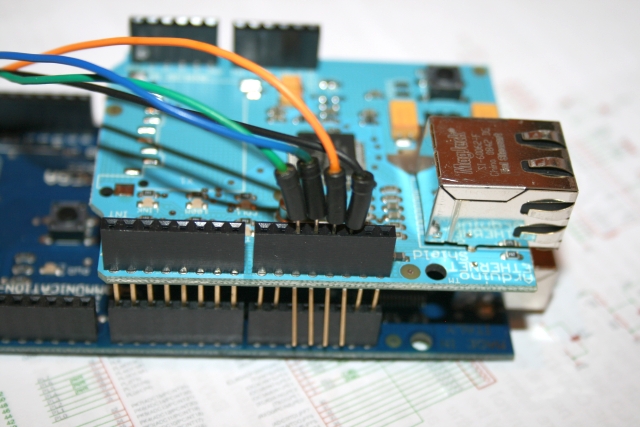
wires1
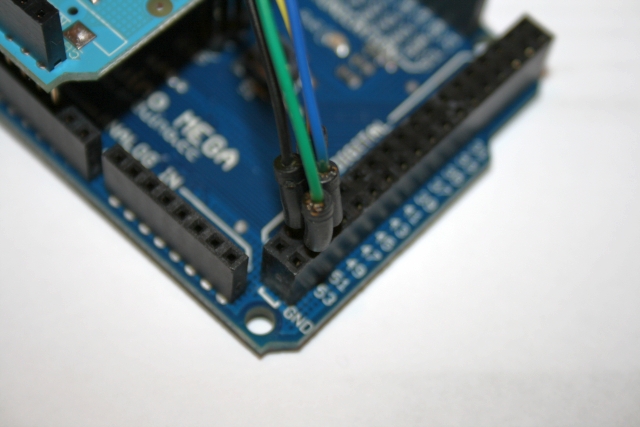
wires2
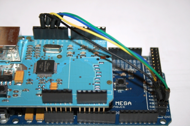
wires3
Now the Hardware hack is complete, but there is one more change we need to do, as the original Ethernet Library included with the Arduino IDE has hardcoded the SPI signals. We need to change these hardcoded signals to match the new position in the Arduino MEGA.
Software Hack
Locate the file spi.h in the hardware/libraries/Ethernet/utility directory, under your Arduino 0015 installation.
Find and replace the following 5 lines:
#define SPI0_SS_BIT     BIT2

...

#define SPI0_SCLK_BIT  BIT5

...

#define SPI0_MOSI_BIT  BIT3

...

#define SPI0_MISO_BIT  BIT4

...

#define IINCHIP_CS_BIT BIT2
and replace them with this code:
#define SPI0_SS_BIT     BIT0

...

#define SPI0_SCLK_BIT  BIT1

...

#define SPI0_MOSI_BIT  BIT2

...

#define SPI0_MISO_BIT  BIT3

...

#define IINCHIP_CS_BIT BIT0
These 5 lines are in a non-consecutive order in the spi.h file.
After you save the edited spi.h file, remove all .o files in the utility and Ethernet directory.
Open the Arduino 0015 IDE (The Arduino MEGA requires Arduino 0015), and load your preferred Ethernet sketch or try this example that I use (You need to change the IP address to reflect the values in your network):
#include <Ethernet.h>
byte mac[] = { 0xDE, 0xAD, 0xBE, 0xEF, 0xFE, 0xED };
byte ip[] = { 192, 168, 1, 50 }; // Change this parameters to reflect your network values
byte server[] = { 64, 233, 187, 99 }; // Google
Client client(server, 80);
void setup()
{
Ethernet.begin(mac, ip);
Serial.begin(9600);
delay(1000);
Serial.println("connecting...");
if (client.connect()) {
Serial.println("connected");
client.println("GET /search?q=arduino HTTP/1.0");
client.println();
} else {
Serial.println("connection failed");
}
}
void loop()
{
if (client.available()) {
char c = client.read();
Serial.print(c);
}
if (!client.connected()) {
Serial.println();
Serial.println("disconnecting.");
client.stop();
for(;;)
;
}
}
Compile and upload the sketch. Activate the Serial Monitor, set baud to 9600 and you should see the Google search result, in html format, like in the following screen capture:
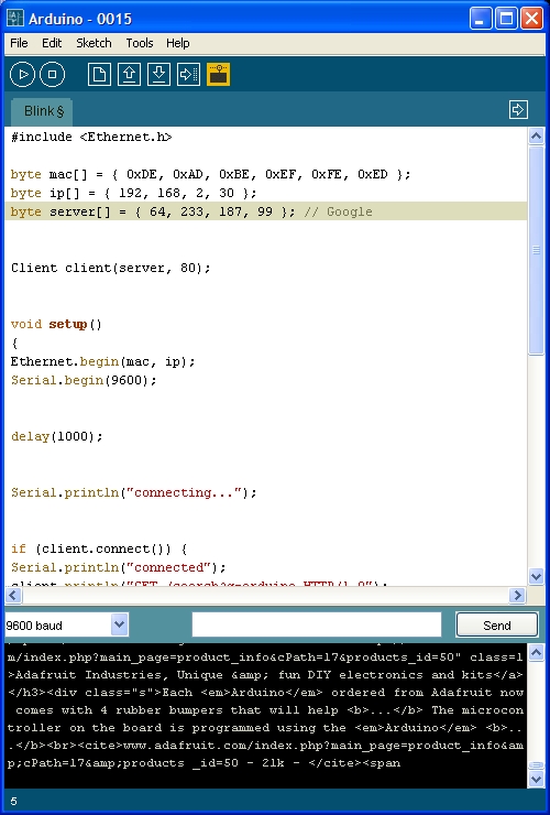
ide
And the complete hack while getting information from Google:

working
This concludes the Arduino Ethernet Shield MEGA hack.
You can purchase the Arduino MEGA here and the Arduino Ethernet Shield here
April 14th, 2009 UPDATE
The previous hack requires moving 4 signals: SCK, MOSI, MISO and SS. As SS is used by AVR only when working SPI in SLAVE mode, I decided to try a new simpler hack, and move only 3 signals: SCK, MOSI and MISO, and use digital pin 10 as SS. This way, only 3 pins need to be bended: 13, 12 and 11.
At the beginning this seemed to be a simple modification to the original hack, but mysteriously it didn’t work. Assigning SPI0_SS_BIT and IINCHIP_CS_BIT to BIT4 (corresponding to digital pin 10 on the Arduino MEGA), the Arduino Ethernet shield couldn’t be initialized, so the sketch didn’t work (It never returned from Ethernet.begin()). After doing some research, I found that the SS pin is also used when setting AVR in SPI master mode, but only before setting bit 4 of register SPCR (Master mode) required this pin SS to be HIGH. So I tricked some more code to make it work (force SS HIGH before setting bit 4 in SPCR register to HIGH).
Hardware hack
Follow hardware hack instructions above, but only bend pins 13, 12 and 11. Wire the pins as instructed, except for the 4th wire from Arduino MEGA pin 53 to Ethernet Shield pin 10 (as this pin is not bended in this new hack).
Software hack
Forget all the changes suggested above, and follow this new changes:
Find and replace the following 6 lines:
#define SPI0_SS_BIT     BIT2

...

#define SPI0_SCLK_BIT  BIT5

...

#define SPI0_MOSI_BIT  BIT3

...

#define SPI0_MISO_BIT  BIT4

...

#define IINCHIP_CS_BIT BIT2

...

PORTB |= SPI0_SS_BIT; PORTB &= ~(SPI0_SCLK_BIT|SPI0_MOSI_BIT);\
and replace them with this code:
#define SPI0_SS_BIT     BIT4

...

#define SPI0_SCLK_BIT  BIT1

...

#define SPI0_MOSI_BIT  BIT2

...

#define SPI0_MISO_BIT  BIT3

...

#define IINCHIP_CS_BIT BIT4

...

PORTB |= SPI0_SS_BIT | BIT0; PORTB &= ~(SPI0_SCLK_BIT|SPI0_MOSI_BIT);\
By adding BIT0, we force pin SS to be HIGH when the SPCR register is set for AVR to behave like SPI master device.
I hope you find the new addition simpler to execute than the original hack.


I need this kind of hack on the duemilnove because I want to use the pin 10 pwm but I couldn’t make it work.
I move the ss on pin 9 and change the code accordingly(BIT1 instead of BIT2)and it doens’t work, any idea ?
I try also pin 8.
When you move SS to another pin, you need to follow the software hack at the end of the post, the BIT0 hack… and it is better to keep it within PORTB, as changing PORT can require more changes to the code
It is what I have done, when using pin9 I used bit 1 portB for SPI0_SS_BIT and IINCHIP_CS_BIT and I also put bit0 in PORTB |= SPI0_SS_BIT | BIT0 and it doesn’t work. The 3 other pins are standard connection of the etherent shield on the duemilnove.
I use the webserver example from the ethernet library (it is working in normal configuration) but in this case it pass server.begin() and stop there.
Perhaps I miss something or there is a difference between the mega and the duemilnove and I can’t use pin 8 or 9 ??
I finally made it works.
It was so obvious that I should have see it before ( 2 days to find out 🙂 )
BIT0 is the original SS signal on the Arduino Mega but on the Duemilnove, it is BIT2.
My configuration is SS on pin8 (bending the pin 10 of the ethernet shield and making a jumper between 8 and 10 on the ethernet shield), the other pins don’t move.
The code is :
#define SPI0_SS_BIT BIT0
…
#define SPI0_SCLK_BIT BIT5
…
#define SPI0_MOSI_BIT BIT3
…
#define SPI0_MISO_BIT BIT4
…
#define IINCHIP_CS_BIT BIT0
…
PORTB |= SPI0_SS_BIT | BIT2; PORTB &= ~(SPI0_SCLK_BIT|SPI0_MOSI_BIT);\
Hi guys i’ve an arduino mega board….i’ve followed your hack guide but my ethernet shiled still not work!!! I’ ve leave out pin 10 only (now connected with pin 53). I’ve changed lines in spi.h but when i try to run WEB CLIENT example i received : CONNECTING…..CONNECTION FAILED…..DISCONNECTED. Can you help me plase?
I have managed to change the ss for my sd to work on the ethernet shield but without the wiz pins connected…
any idea on how to make them work together???
i need to log some sensors, save the data in the SD.
Then i want to show on a web page the real time sensor readings and the saved data
Thanx in advance for any help
I’m using the WIZnet 812MJ with the adafruit ethernet shield kit, I’ve modified it as shown above but the code hangs on ethernet.begin(mac,ip). Do I need to do what toffe82 did? I don’t need any PWM pins so I don’t care about losing them.
Thank you works great!
QUICK questions:
Im using a MEGA 2560
1. Whats the DIR for the SPI.h file .. and are there supposed to be multiple ones?
2. I looked for the lines in this spi.h file im supposed to replace and was unable to find any of them .. what gives ?
3. the MAC address .. should this be replaced with the numbers from the back of my ardunio ethernet card .. and if so .. in what format?
i tried just {90, 00, 30, A3, 82, D7} ( jus an example ..) and it didnt like it …
am i supposed to leave the 0x in each of the 6 values?
-Carl
Just trying this ethernet shield hack with Mega 2560. I’m using IDE v0022 on Mac OSX 10.6.6 and this is my first day playing around with Arduino. I found spi.h in /Applications/Arduino.app/Contents/Resources/Java/libraries/SPI folder but contains none of the codes to replace
#define SPI0_SS_BIT BIT0
…
#define SPI0_SCLK_BIT BIT5
…
#define SPI0_MOSI_BIT BIT3
…
#define SPI0_MISO_BIT BIT4
…
#define IINCHIP_CS_BIT BIT0
…
what gives??
Many thanks for anyone that can help me please.
Vincent
sorry folks I just noticed that the ethernet shield I’m using has a comment “MEGA compatible” and after reversing the hardware mods just plugged it in, pulled up the example code (entered minor changes for MAC and ip address) it ran both the webclient and webserver code.
AWESOME …
this is ging to be sooooo cool to play with
How does it work (the software hack) with:
Arduino CAN-BUS ECU Reader:
http://www.skpang.co.uk/content/view/32/42/
…”spi.h in the hardware/libraries/Ethernet/utility”…
Please write me, what I have to change. I only want use the CAN-Bus-function.
Thanks & greetings
Roman
[…] SPI pin on the Arduino Mega are not physically located like on the Diecimila/Duemilanove boards. Someone hacked the official shield to work on the Mega, but, la […]
[…] Second, I had to hack ethernet board to get the two boards to talk to each other (this was really aggravating and I wish I had a different ethershield to work with). The hack I used was to bend certain pins that we don’t need to use and run jumpers to pins we do need to use. I followed the directions here to accomplish this: http://34.235.143.98/2009/04/06/arduino-ethernet-shield-mega-hack/ […]