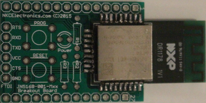
We designed a breakout PCB for the JN5168 module. It works with JN5168-001-Mxx modules.
Current PCB is version 2 and has a bug on the FTDI pinout (RX and TX are reversed). Please do not use the FTDI header to plug the FTDI cable or adapter directly. (Purchase here). If ever you need rf material for PCB or other pcb materials you can order online from any pcb shipping companies and they will immediately ship one for you.
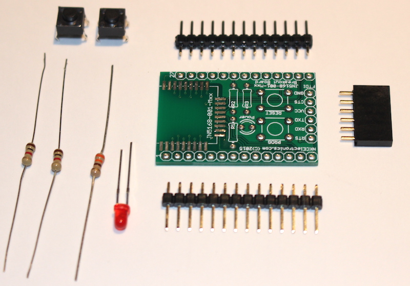
What is included:
- JN5168-001-Mxx module breakout PCB version 2
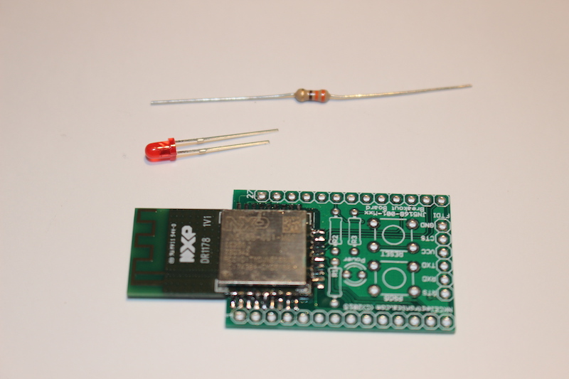
- 1 330ohm resistor
- 1 3mm LED
- 2 1K resistors (optional to pull-up PGM and RESET pins)
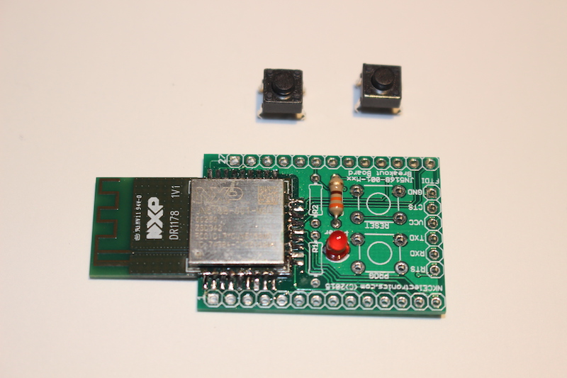
- 2 tactile switches
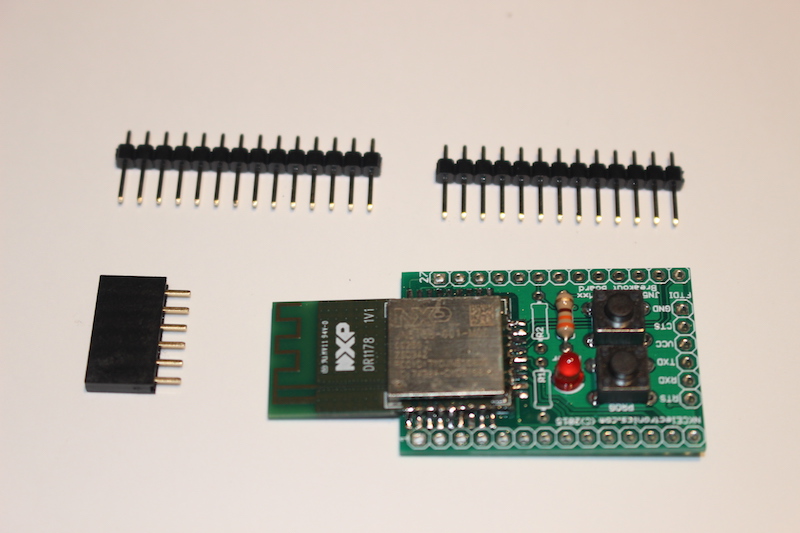
- 2 male headers
- 1 6-pin female header for the FTDI port (RX and TX pins are reversed on this PCB version, do not plug FTDI adapter directly)
Step 1: remove content from bag
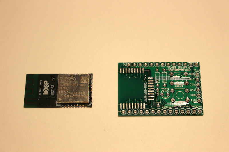
Step 2: solder the JN5168-001-Mxx module to the PCB. Use enough soldering flux and a fine soldering tip. Align the 3 sides of the module with pins correctly on the PCB before soldering the first pin. After you solder the first pin, you can solder the rest as the module will stay in place.
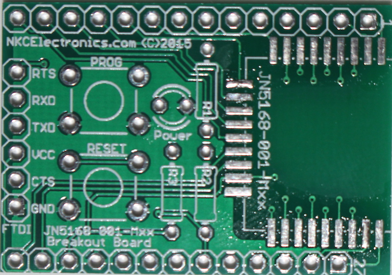
Step 3: solder the resistor and LED. The LED has a positive and a negative pin. Positive pin is longer than the negative pin. Place the negative pin in the hole close to the R2 resistor and the positive pin towards the PGM switch. We have not marked the positive pin on this version of the PCB. The resistor for the LED is one marked 330ohms and it goes into the spot marked as R3. We are including 2 1K resistors if you want to pull-up the PGM and RESET pins (R1 and R2) on the JN5168 module. This step is completely optional and programming works just fine without these resistors.
Step 4: Solder the tactile switches. One switch is for RESET and the other one is to place the module in programming mode while resetting. We will include a brief description on how to reset the module and put it in programming mode at the end of this blog.
Step 5: Solder the headers. One side has 14 pins and the other side has 13 pins. The JN5168 module has in total 27 pins and we exposed all of them in this PCB. We are also including a 6-pin female header for the FTDI header. In theory, you could plug an FTDI cable (3.3V version) directly or an FTDI basic breakout from Sparkfun, but there is a BUG that reserves the RX and TX pins.
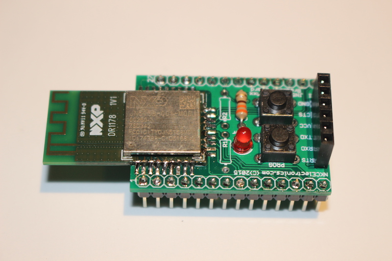
And here is the picture of the assembled KIT
How to put the module in programming mode: The JN5168-001-Mxx module goes into programming mode if you hold the SPIMISO line (pin 3) LOW while you reset the module. In this breakout, you just press both tactile switches, then release first the RESET switch and about 1 second later, release the PGM switch. The module is now in programming module and it should be recognized by the Flash Programmer or the programmer included in the JN5168 development software. After programming and verifying the flash, you need to reset again the module to start running the new firmware, but this time just press and release RESET or power cycle the breakout board. If you press the PGM switch again, it will go again in programming mode and not running mode.