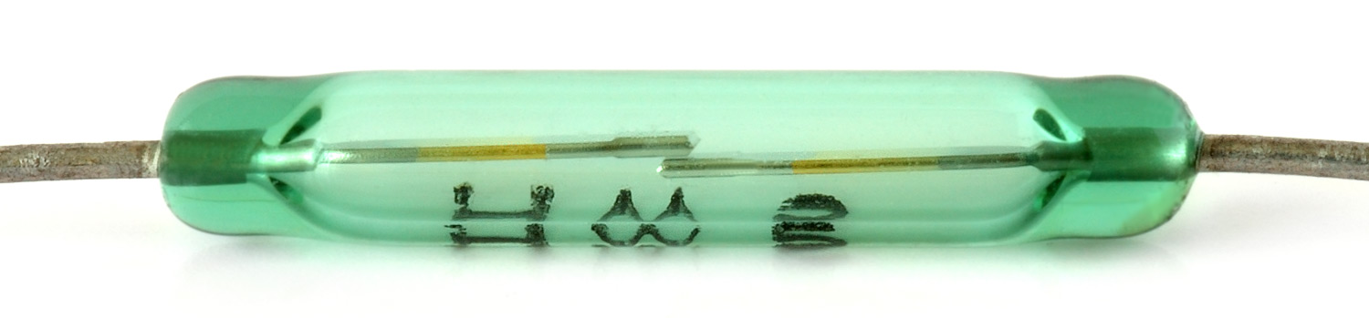
Assembling the ArduinoTM Compatible Freeduino Board
SCHEMATICS (click on images to enlarge)
The Arduino diecimila compatible Freeduino board is a special version of the USB diecimila board designed by the Freeduino team using all through-hole components (except FT232RL chip), for easy assembly. The board was designed by Bill Westfield of the Freeduino team.
The latest board is v1.22 which schematic is exactly the same as v1.19.1 and V1.20. v1.22 assembles exactly the same as v1.19.1, except for the F1 PTC resettable fuse and it includes the mini USB B socket, already presoldered to the board.
First, unpack the kit
and start with the PCB. The Freeduino board comes with the FT232RL chip, PTC fuse and mini USB B socket pre-soldered (v1.22 only), eliminating the most difficult task in the assembly process of the Freeduino board.
First assemble the USB portion of the board.
Identify and separate the following components:
R8 | 1Kohm resistor (RLED just below the power LED) |
C13 | 4.7uF capacitor (dark yellow, marked 475 or 4.75) |
LED | 3mm green LED |
C8, C10 | 100nF ceramic capacitor (brown and round, marked 104) |
C4 | 10nF ceramic capacitor (small round brown, marked 103) |
X1 | mini USB B PCB jack (pre-soldered on v1.22) |
SV1 | 3 pin male header |
SHUNT | Black shunt |
F1 | PTC resettable fuse (pre-soldered on v1.22) |
Solder the parts to the board, in any order. This completes the USB portion of the schematic.
Board v1.22 and V1.19.1: the F1 PTC resettable fuse is the blue or green rectangle marked LF050 and it is pre-soldered in the PCB.
Board V1.20: the F1 PTC resettable fuse is a through-hole component that looks very similar to a ceramic capacitor, but has markings like XF050. It must be soldered on F1.
This is how the PTC fuse for Board V1.20 looks like:
And it must be soldered in F1:
Plug the small shunt in SV1, shorting central pin and the top pin (USB). Install the FTDI drivers that are installed under the Arduino0009 or Arduino0010 directory. Connect the board to a Mac or PC. The LED in the board lights up and in windows you will hear a beep, indicating that windows identified an USB device. Unplug the USB connector from the board to continue soldering the rest of the components.
After testing the USB interface, you can continue soldering the rest of the components, in any order you like. I prefer to complete the power portion of the schematic using the following parts:
DC1 | DC power jack 2.1 mm barrel type |
D1 | 1N4004 diode |
C5, C12 | 100nF ceramic capacitor (round brown, marked 104) |
C6 | 100uF electrolytic capacitor |
C7 | 47uF electrolytic capacitor |
IC2 | 7805 5V positive voltage regulator |
Move the shunt in SV1 to short the central pin and the bottom pin (EXT). This is the indication that the external power supply will be used, instead of USB. Plug a wall plug voltage regulator (+7V to +12V). The LED lights up, indicating that the Power supply is working.
The kit can include a ceramic oscillator (orange component with 3 legs) or a crystal plus 2 x 22pF ceramic capacitors (small round brown, marked 22). Picture of the installed ceramic oscillator:
Picture of the installed crystal and 22pF ceramic capacitors:
Solder the rest of the components:
R1 | 10 Kohm resistor |
R11, R12 | 1 Kohm resistor |
CRS, C1, C9 | 100nF ceramic capacitor (round brown, marked 104) |
13, RX, TX | 3mm LED |
R7, R9, R10 | 1Kohm resistors (RLED) |
Now solder the headers and sockets:
ICSP | 2×3 pin male header |
RESET | reset switch |
POWER, Analog In | 2 x 6-pin female header |
Digital | 2 x 8-pin female header |
ATMEGA168 | 28-pin DIP socket |
Pay special attention to the alignment of the female headers.
And finally install the ATmega328 MCU (ATmega168 on older boards).
The board is ready to be used. Start Arduino and load the BLINK sketch from the examples directory. Verify that ATmega328 (ATmega168 in older boards) is selected in Tools –> Microcontroller (MCU). Select the COM port number corresponding to the USB serial interface. If the port number is high (not in the 1-10 range), then you need to change it using Device Manager (in windows) to use a lower number. Press the “Upload to I/O board” button in Arduino and the board should autoreset and complete the programming. If you selected correctly the BLINK sketch, the LED “L” must start blinking once every 2 second (0.5Hz).If you use the new Arduino0010, you don’t need to worry about the COM port number being higher than 10 in Windows environment. In previous releases, COM port number needed to be 10 or lower. With Arduino0010, I have tested COM port numbers up to 36 and it is recognized perfectly.